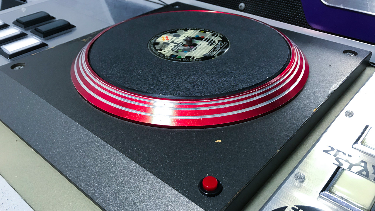
On this page, I summarize the structure and behavior of beatmania’s characteristic input device: the turntable.
The information I’ve summarized mainly pertains to 5-key beatmania’s turntable, but it also explains some parts of IIDX’s, which has the same structure.
Structure of the turntable
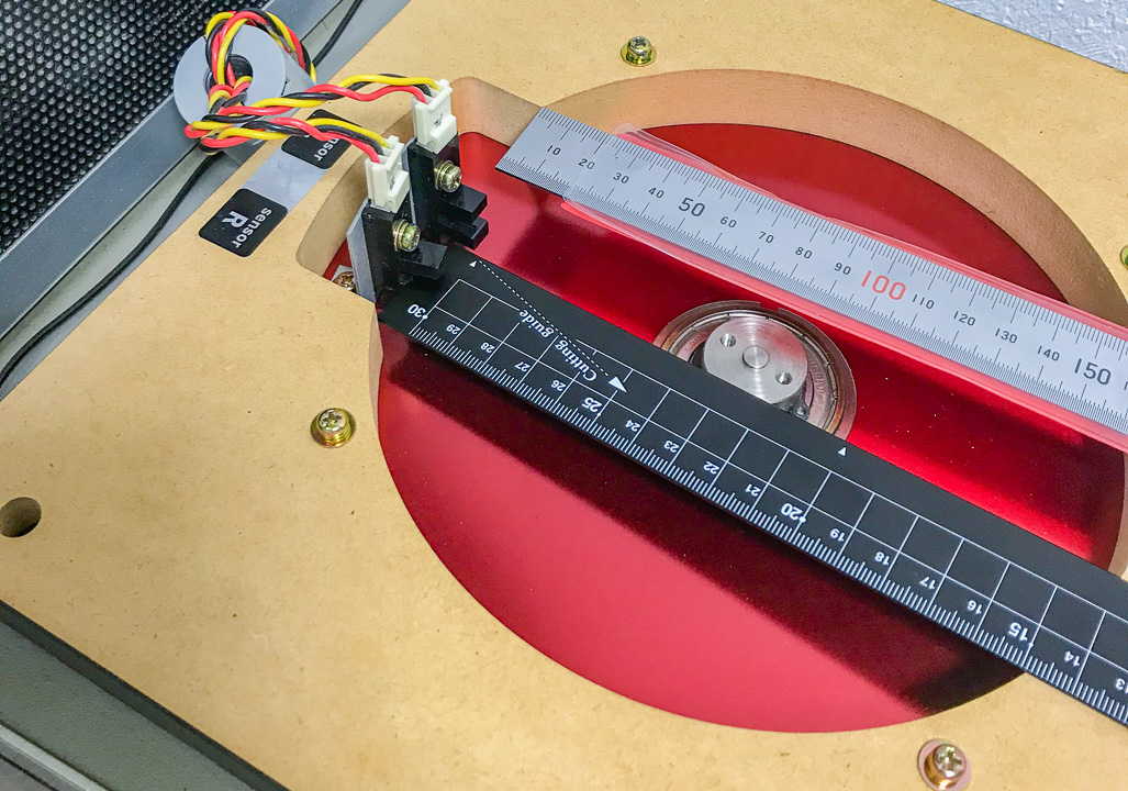
A gear wheel and photointerrupters are used within beatmania’s turntable.
The structure is pretty much the same across the original beatmania (5-key) cabinet, IIDX cabinet, and various CS controllers.
The lone exception is beatmania III’s turntable.
I don’t know too much about it, but apparently it uses a rotary encoder?
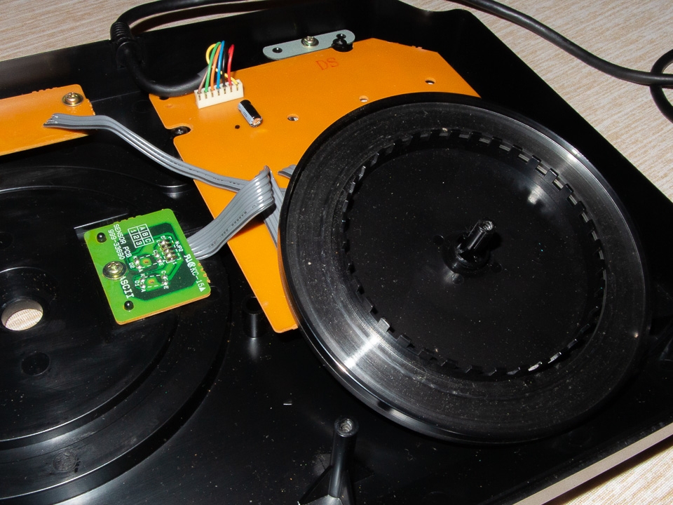
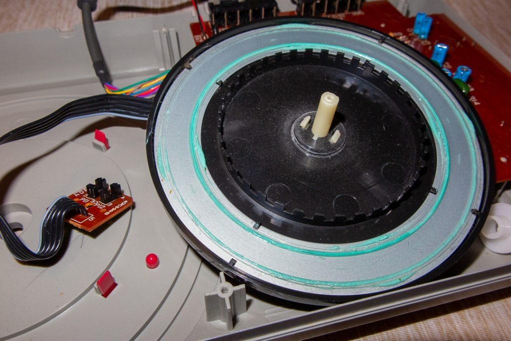


Gear wheel
The gear wheel is a platter containing slits that are evenly spaced.
On original 5-key beatmania cabinets, its turntable has 72 slits.
The turntable appears to detect rotation at a 360°/72 = 5° interval.
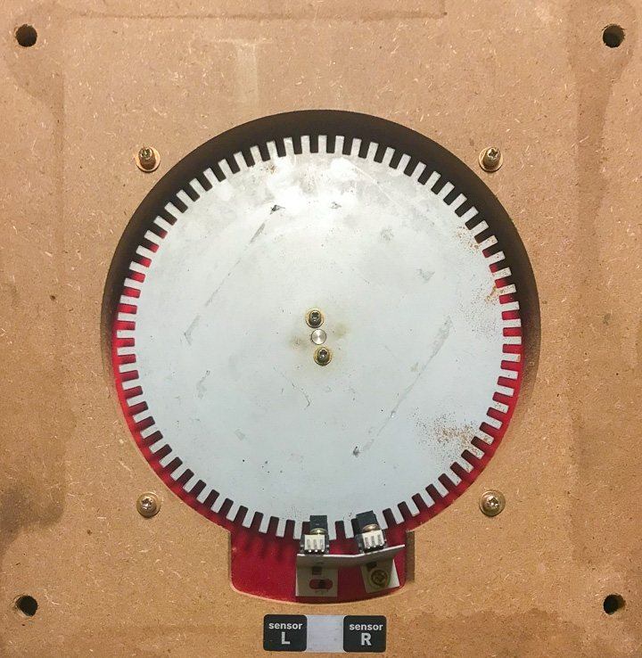
In CS controllers, the turntable slits are in a perpendicular position, due to the reduced space.
The ASCII controller and DJ Station Pro both have 36 slits on their turntables, half the number of slits on an AC turntable.
Therefore, it detects rotation at a 10° interval.
The CS IIDX controller has 50 slits, so its turntable appears to detect rotation at a 7.2° interval.
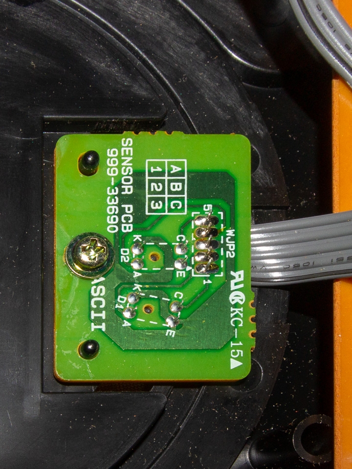
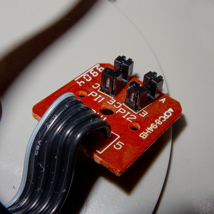
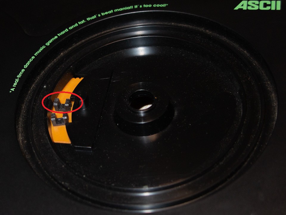
Photointerrupters
These sensors detect whether something is blocking the gaps, through a combination of light-emitting diodes (LEDs) and photoreceiver optical sensors.
The sensor component on its own is sometimes referred to as a “photosensor,” “photodiode,” “phototransitor,” or some other term.
Although the term “photoreflector” is somewhat similar, it’s different in that it detects the emission of light, not the obstruction of it.
Here on this page, I refer to the whole unit as a “photointerrupter.”
The AC turntable appears to use an “F”-shaped photointerrupter.
Examples of model numbers are TLP1201A (from Toshiba) and GP1A22HR (from Sharp).
Both of these operate off of 5V.
CS controllers use something like an RPI-441C1? Separate power is applied to the sensor component and the LED component.
3.3V is applied to the sensor component, while 1.14V is applied to the LED component, due to electrical current constraints.
On both AC and CS, the voltage reads as High when light is obstructed.
Detecting rotation
By placing two photointerrupters so that their pulse phases are 90° apart (1/4 of the wavelength), the turntable can detect the direction of rotation.
Here are figures of what the gear wheel looks like. They are mostly to scale.
(Click to expand)


Let’s observe the state of the left sensor during the moment that the right sensor turns red.
The moment that the right sensor turns red during counterclockwise rotation, the left sensor is blue.
The moment that the right sensor turns red during clockwise rotation, the left sensor is also red.
By checking the state of the other sensor when one sensor changes, the turntable can determine the direction in which it is rotating.
Processing detected signals
AC
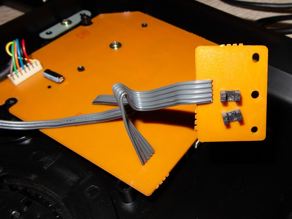
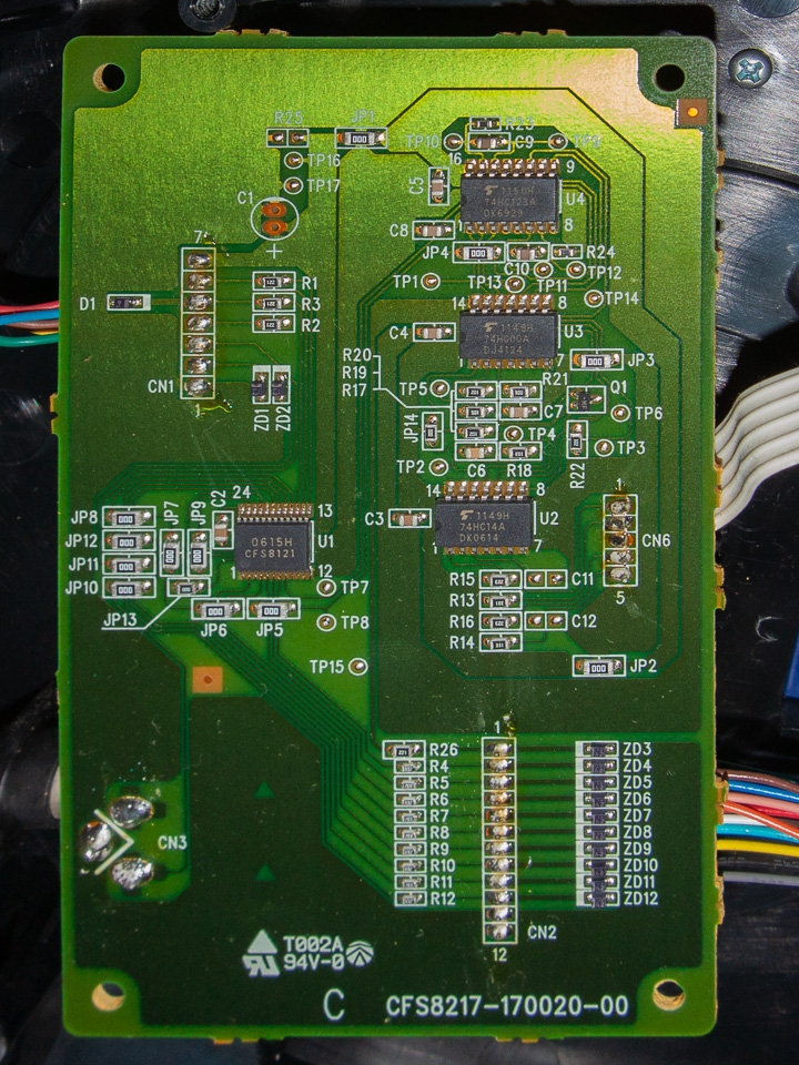
On a 5-key beatmania cabinet, a turntable has a dedicated sub-board that processes turntable signals.
In the examples above, we observed the right sensor when the signal rises (when it turns red),
but in reality there are four areas where the turntable could detect the direction of rotation:
・Leading edge in left sensor
・Leading edge in right sensor
・Trailing edge in left sensor
・Trailing edge in right sensor
However, when I tried testing them on actual hardware, it appears that almost exclusively the leading edge in the right sensor is used (the same pattern from the examples), although there were a few instances of exceptional behavior.
Supposing that a turntable detected signals at all of these timings, you could create one that is 4x as sensitive as actual hardware (and would detect a signal every 1.25°).
It would respond just by placing your hand on it, and a 1-turn scratch would be completed at 90° (lol)
Something resembling a LAN cable extends out from the sub-board, and it uses serial communication to send the current rotational position to the main board.
I did do some research on the communication, but I will write about it in another entry, since it would make this one longer.
CS
CS also detects signals using an edge on one side, just like AC, but it uses the trailing edge instead.
The sensors are in the same position on an ASCII controller, DJ Station Pro, and IIDX controller (when the turntable is on the right), and the trailing edge is for the sensor on the upper side.
The turntable basically works the same way as it does on AC, but it doesn’t keep track of the rotational position.
It merely sends an Up or Down input on the controller, depending on the direction of rotation.
The turntable is designed so that it continues to output a signal in the same direction for a certain length of time, so that it doesn’t cut off the signal when you rotate it continuously in the same direction.
To me, this length of time feels a little long.
Most likely this length of time lasts 200ms or longer, so in charts on AC where you can quickly scratch in the same direction, you can’t do so on CS.
In conclusion
When you understand how the turntable works, you can apply that knowledge by:
- Creating a homemade detector for CS to make it easier to quickly scratch in the same direction
- Using an AC turntable on CS
- Using a CS turntable on AC
I will be going through these kinds of things in subsequent entries.
コメント