Overview
beatmania’s distinctive turntable devices are controlled by a sub-board.
The main board doesn’t have the ability to directly control turntable inputs, so without the sub-board, turntable inputs can’t be read at all.
Because sub-boards are rarely seen in auctions or elsewhere, if your sub-board fails, or if you only have a main board, the turntables become unusable and the game effectively becomes unplayable.
For this project, I created a replica board that’s compatible with this sub-board.
I named it “CONMP Board,” as a play on “CONP” (control panel board, similar to the naming in IIDX) and “COMP” (for “compatible”).
About the board
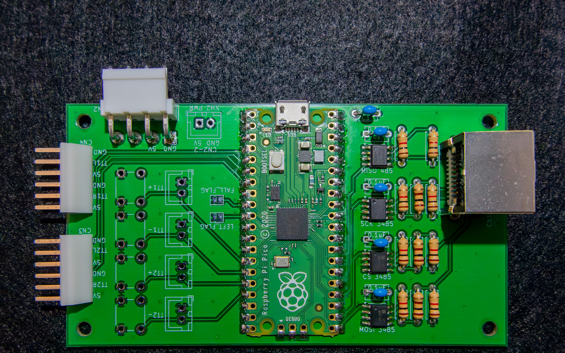
I designed the CONMP board based around a Raspberry Pi Pico.
The connectors are the same type as those on the original board so that you can reuse the existing wiring if you’re replacing the original board.
Power supply
The board operates at 5V. There are three ways you can supply power to it:
- VH connector
For reusing the original wiring. Use this if repurposing from an original board. - XH connector
A commonly used connector.
This is available so that if no original wiring is present and you’re providing the wiring yourself, you can use this connector, which is easy to obtain. - Micro USB on Raspberry Pi Pico
USB port on the microcontroller board.
Used for programming and debugging output, but it can also serve as a power supply input.
Please use only one of these methods at a time. The design does not expect multiple power sources to be used simultaneously.
Wiring connections
The wiring to the turntable sensor uses an NH 6-pin connector.
The pin assignments from pin 1 onward are:[5V][R sensor][GND][5V][L sensor][GND]
Connect the 1P wiring (connector CN33 if using the original cable) to CN4.
Connect the 2P wiring (connector CN34 if using the original cable) to CN3.
An 8P8C (LAN connector) is used for communication with the DJ MAIN board.
Use an STP LAN cable for this connection. If you’re not sure, choose a CAT 7 LAN cable.
BOM (bill of materials)
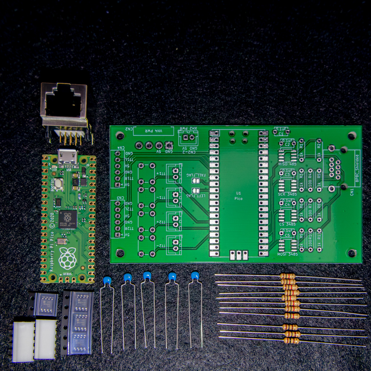
The links are to retailers, for reference. You don’t necessarily have to purchase the ones in the links.
Items marked with “*” under “Qty” are optional and should be installed as needed.
| Reference | Qty | Value | Note |
|---|---|---|---|
| C1-C5 | 5 | 0.1uF | Decoupling capacitors |
| CN1 | 1 | 8P8C | LAN communication connector |
| CN2 | *1 | B4PS-VH | 5V power connector (for original wiring) |
| CN2-2 | *1 | B2B-XH | 5V power connector (for custom wiring) |
| CN3-CN4 | 2 | BS6P NH | Sensor connection |
| J1-J4 | *4 | B2B-XH | Debug button external connectors |
| R1-R3, R5-R6, R8-R9, R11 | 8 | 1kΩ | Pull-up/pull-down resistors |
| R4, R7, R10 | 3 | 100Ω | Terminator resistors |
| SW1-SW4 | *4 | Tact switch | Debug buttons |
| U1 | 1 | Raspberry Pi Pico | MCU |
| U2 | 1 | MAX485ED | 5V-driven MAX485 (transmit) |
| U3-U5 | 3 | MAX3485ED | 3.3V-driven MAX485 (receive) |
Sensitivity settings
Normally, rotation is detected only on the rising edge of the right sensor, and incremental/decremental counting is performed (the original behavior).
By shorting jumper pads on the board, you can change the setting and increase detection frequency:
- Short “FALL_FLAG”
Also detect on falling edges (x2 sensitivity) - Short “LEFT_FLAG”
Also detect using the left sensor (x2 sensitivity) - Short both “FALL_FLAG” and “LEFT_FLAG”
Detect via both sensors on both rising and falling edges (x4 sensitivity)
The AC turntable has 72 teeth on its gear, so detection occurs once every 360°/72=5°.
If for example you created a turntable by modifying an ASCII Con, it would only have 36 teeth (1 detection per 10°), which means you’d need to rotate the turntable twice as far to make the game detect the proper angles when selecting a song or doing a 1-turn scratch.
By setting the sensitivity to x2, even a turntable with a 36-tooth gear can be detected every 5°, like the AC turntable is.
Differences from the original
I’ve tried to replicate the original behavior as much as possible, but have confirmed the following differences:
Misfiring improvements
On the original sub-board, when rotating the turntable in the opposite direction of the last rotation, it momentarily detects in the forward direction.
This causes a bug in 1st-3rd MIX where during push/pull movements, it overreacts and results in extra POORs.
In completeMIX onward, the programming was changed so that this is suppressed.
The CONMP board makes precise detections, which prevents these misfires.
While this is a good thing for gameplay, you could also see it as not being able to reproduce the original behavior when using it for 1st-3rdMIX.
Value corruption
On rare occasions, an incorrect turntable value may be returned.
The main board communicates with the sub-board to query the turntable value.
If the CONMP board’s internal processing doesn’t respond in time and can’t provide the correct value, it returns an incorrect value.
Since querying happens once per frame, it typically returns to the correct value on the next frame, but during gameplay a split-second changed value might be detected as a scratch.
I’ve reduced the frequency of it through software improvements, but I haven’t verified that it’s been fully eliminated.
Debug buttons
You can attach buttons that increment or decrement the current turntable value.
In addition to directly mounting tact switches on the board, you can also route external wiring via an XH 2-pin connector.
These could be useful for basic board operation checks, or for building a reduced-space control panel.
Sales info
Currently for sale on BOOTH.
DJ MAIN用サブ基板互換 CONMP基板 [LAY-004-01] | BOOTH
Source code and firmware
The source code is uploaded to Lay31415/LAY-004-01 | GitHub
Installing the firmware
- Download the prebuilt firmware
LAY-004-01.uf2from Releases. - Connect a USB cable to the Raspberry Pi Pico while holding the BOOTSEL button.
- The device is recognized by the PC as a USB drive named
RPI-RP2. - Drag the downloaded file,
LAY-004-01.uf2, to theRPI-RP2drive to copy it over. - The file will automatically be written and the board will restart.
After the file is written, the board can start operating as a replacement for the Sub PCB.
コメント